- Craig Andrews
- Category Serial - Parallel I/O
Well, I really pulled a boner by not reading the RTC specification sheet for the SPIO board and it came back to bite me.
Since I was going to submit boards in a couple of days, I did a quick design and layout of the Serial – parallel I/O board and slapped on a RTC with just a quick glance of the spec sheet. I could not see how they were decoding the internal ports but this was no time for learning or wading through pages and pages of blah blah blah. My plan was to figure that out when I sat down to start programming the RTC.
Well, the good news is that the 8251 USART works (thanks to Jack who caught a mistake in the baud rate clock), the 8255 works, and the onboard home brew I/O port works.
The bad news is that not reading how the spec sheet made the RTC a total failure. When I first looked at the specs it seemed too ridiculous to imagine that the chip actually took 128 I/O port addresses. I figured that there must be some sort of internal pointer that was loaded to determine which of the internal ports was being accessed but, nope, the chip actually takes half of the available 8085 port addresses.
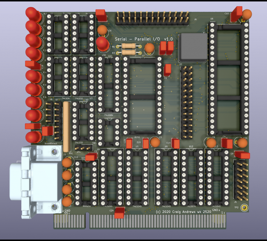
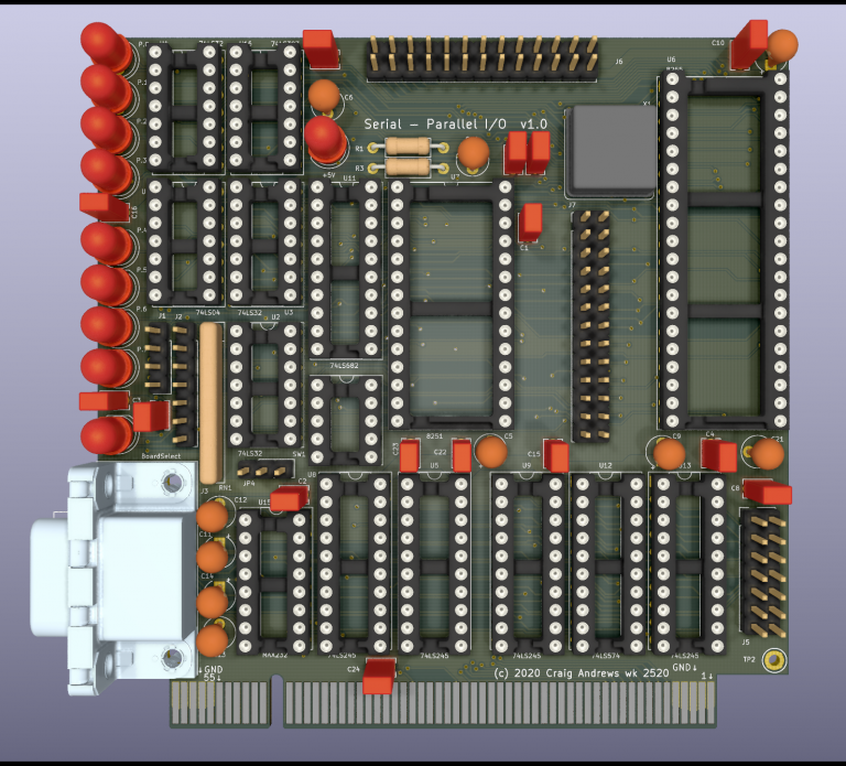
Yes, I could have either memory mapped the I/O (so the registers could have just been read as memory addresses), or I could have put in a ‘pointer’ port that would be loaded to then determine which port is actually being addressed. However, either of these would require a complete re-layout of the board and I was a little too disgusted at the RTC design to put any more effort into the parallel RTC. I2C RTCs are readily available and just as useful, so I just bagged the RTC portion and replaced it with an expansion port header.
This header can be used with the Port Protoboard for off-board prototyping. The port address is already decoded and all the unused gates are brought to the prototyping header. In the end, even while the RTC was a disaster, the board should be a handy tool for experimentation.


