- Craig Andrews
- Category Bus Monitor Supreme
There is a key point regarding the data breakpoint that I have glossed over but it will certainly be noticed when that feature is used.
When the Address Breakpoint is used, the LED and 7-Segment displays make it obvious that the 8085 was stopped right at the specified (i.e., breakpoint register loaded) value. However, when the same is done for the data, the displays make it painfully obvious that the data bit pattern does not match the breakpoint value. In fact it would be extremely rare for the data value displayed to match the breakpoint value. The only time the target value is displayed is if low byte of the program counter address of the next instruction happens to match the target data breakpoint bit pattern set in the data breakpoint register.
To put your mind at ease, the bus monitor DID see the match and immediately set the stop-for-step trigger as soon as the matching data byte moved through a port or a memory location (including if the data byte happened to be the opcode itself).
The problem is that while the bus monitor immediately took the READY line low, the 8085 isn’t looking at the READY signal during most of those times. The reason the bus monitor can stop exactly at the breakpoint address is because the CPU gates in the READY line right after the address is placed on the bus. So in the grand scheme of things, there is actually a small window of opportunity to put the 8085 into a wait state. After all, the purpose of the wait state is to allow a memory or I/O device to catch up with the CPU and that is only required after the CPU has put the address on the bus. The end result is that even if the READY was taken low at some arbitrary point during a machine instruction, it is not until the beginning next machine instruction that the 8085 evaluates the READY.
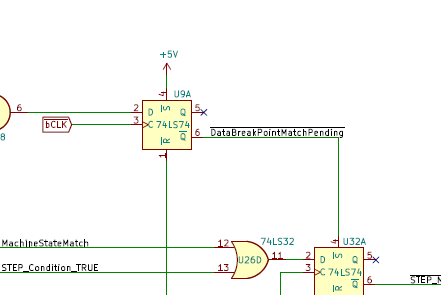
This is the reason the signal on the bus monitor coming out of the U9A latch is called DataBreakPointMatchPending* because it has recognized that a data match has occurred, but the actual 8085 WAIT state will happen sometime in the future. So a data match takes the DataBreakPointMatchPending* active (low) and the READY line is immediately taken inactive (low). The 8085 then finishes that machine instruction and enters the STEP mode at the beginning of the next machine instruction when it gates in the READY signal.
The end result in operation is that when the Data Value Breakpoint feature is used the CPU will enter a wait state but, confusingly, the display will not match the target bit pattern.
Perhaps I should rename that feature a Data Bit Pattern Coasting Point rather than Break Point so that future-me isn’t confused the next time I re-forget this little detail.

