- Version 1.0.6
- Download 148
- File Size 320.26 KB
- File Count 1
- Create Date March 5, 2022
- Last Updated April 12, 2022
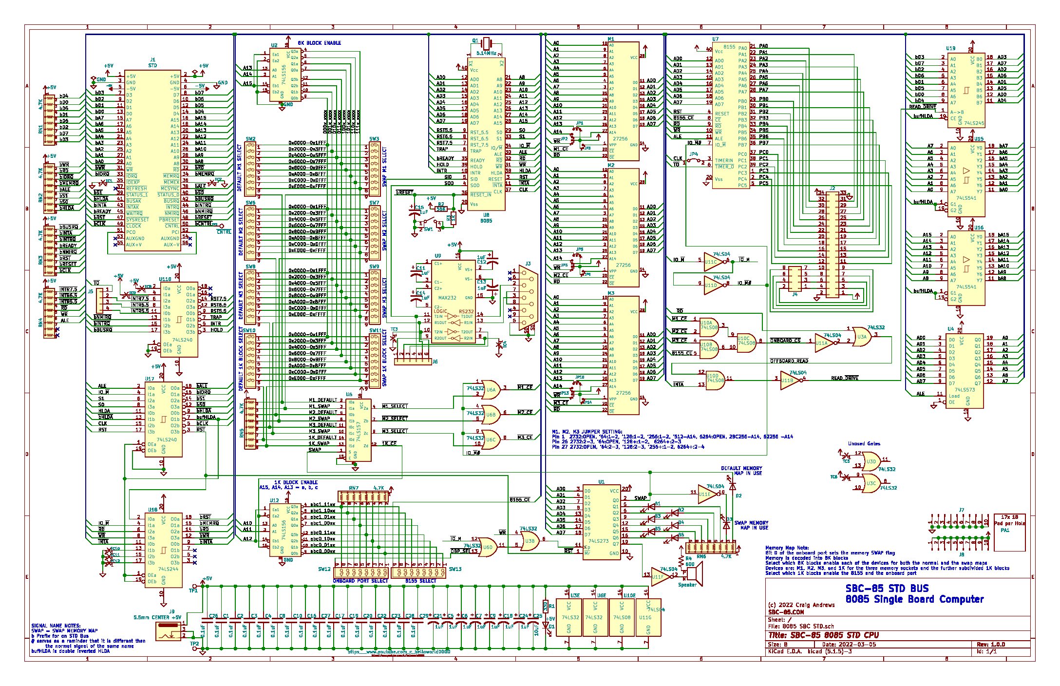
STD Bus 8085 SBC V1.0.6 Schematic
3-6-22 UPDATED SCHEMATIC TO CORRECT CROSS SHORT ISSUE AND POLARITY OF C12 ON MAX232. Added reset supervisor, freewheeling diode on speaker/relay output.
3-9 Additional refinements, some diagnostic labels and other clutter still left behind
4-12-22 Schematic as submitted to PCB fab house


On the max232 I think C12 is the incorrect polarity. Output on pin 2 will be > 5V.
I like the memory switching but there looks like there could be an interaction between the main and swap blocks when larger than 8k blocks are mapped. e.g. I you had say a 8k EEROM and 32k RAM. If the initial mapping was 0x0000-0x1fff EEROM and 0x2000 – 0xa000 so SW2 1 closed and SW5 2,3,4,5 closed. Say you wanted swap map with RAM now at 0x0000-0x8000 so SW7 1,2,3,4 closed. With this switch configuration the switches will connect Q0B, Q1B, Q2B and Q0A lines together regardless of the bank selected and you have an address clash in both configurations. I am not sure if this is a valid configuration. You can avoid the conflict by never changing the size of a memory block only its function. It might be possible to put some diode isolation between the main and swap selection switches. Perhaps what you could do is duplicate U2 and only enable the 3 to 8 decoder depending if in swap mode or not. This might mean you can remove U5 so there is no chip count increase. This also removes one gate delay in the address decoding path.
I created a new max232 because the one in KiCAD was 5 times larger than any other chip, but I have done that chip so many times I didn’t even check it for mistakes. Thanks for pointing that out!
As for the cross shorting of the switches, you are right, that was a bone head mistake and I like you4 idea of doubling the encoders and dropp8ng the multiplexer.
Good catches on both and the first to point out this glaring error.
What STD board would like?
I noticed that some parts in KiCAD are huge. It makes for a much cleaner schematic when you redo these symbols.
When I was a University I remember using a Z80 STD bus board for some lab experiments. We had some wire wrap STD expansion boards to wire up some IO expansion stuff. It was a great introduction to embedded systems. We were using a C cross compiler hosted on a unix minicomputer and you push the compiled binary code to the boards with xmodem I think. I have recently been doing work on a Jetson Xavier so everything is hosted on the couple of hundred dollar development board.
If you have a spare CPU card that would be neat but if the postage to Australia is going to be a killer then don’t worry about it. I will keep an eye on your design an maybe pickup a board when you have completed it.