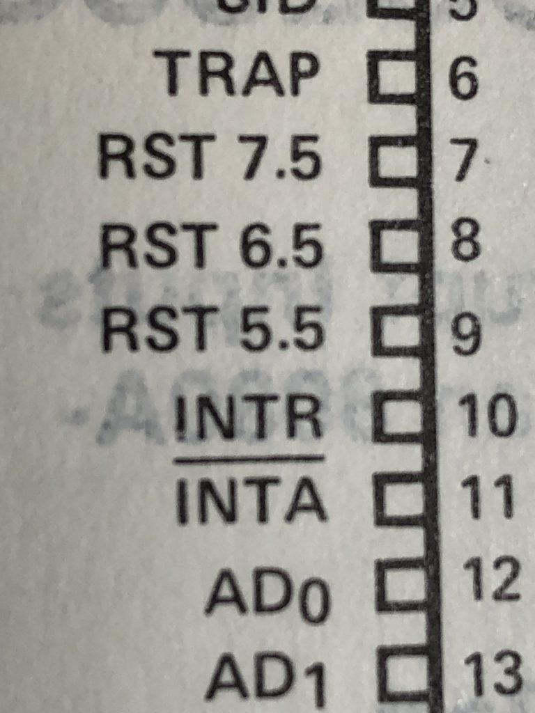
Hardware interrupts are simply signal inputs that are monitored by the CPU and when one (or more) is triggered, the CPU responds by calling a subroutine. That subroutine call allows the program to deal with whatever needs to be dealt with, and the code can then return back to where it left off. Intel introduced the basic interrupt concept with their 4040 but the ‘Hardware Interrupts’ built into the 8085 gave the concept significantly more power than its predecessors.
To expand on the basic concept, the 8085 has FIVE hardware interrupts: TRAP, RST 7.5, RST 6.5, and RST 5.5. Why these are named as such we will get into into a later post. For now, simply understand that each of these hardware interrupts are represented by an input pin on the 8085 (pins 39, 7, 8, and 9 respectively) and when the signal is (or possibly becomes) active the 8085 will call a subroutine that is at a hardware defined location. For example, when the 8085 detects that the RST 6.5 input is high AND the interrupts are enabled AND the RST6.5 interrupt is visible (i.e., not masked), THEN the 8085 will perform a CALL to whatever subroutine is at address 0x002C. In a similar fashion, when the CPU hardware for RST7.5 is tripped the 8085 will CALL the subroutine at 0x003C. However, RST7.5 is not LEVEL triggered like RST6.5, it is rising EDGE triggered, i.e., a RST7.5 will only trigger the 8085 if there is a low-to-high transition presented at the RST7.5 input.
The full interrupt table for the five interrupts is as follows:
- TRAP (Rising Edge and Level) –> 0x0024
- RST 5.5 (High level until sampled) –> 0x002C
- RST 6.5 (High Level until sampled) –> 0x0034
- RST 7.5 (Rising Edge, latched) –> 0x003C
The next important concept is that (except for the TRAP) the hardware interrupts can be Enabled or Disabled with the EI and DI assembly instructions. Primarily reserved for BIG events (e.g., system power is about to fail), the TRAP interrupt cannot be disabled and is always active, so if you don’t want to use it the line needs to be tied low.
Also note that interrupts have a priority, with TRAP being the highest priority, then RST7.5, then RST6.5, and finally RST5.5. This means that if multiple interrupts are detected at the same time, the CPU calls the subroutine for the interrupt with the highest priority.
When these hardware interrupts were introduced with the 8085 they were also given the ability to individually control which interrupts are visible to the processor, i.e., which ones will be addressed and which will be ignored. So while the EI and DI instructions turn ALL the interrupts on and off, the SIM instruction provides one-by-one of which interrupts are visible and which are ‘masked’, i.e., invisible and ignored.
Finally, note that when interrupted the CPU calls a subroutine rather than jumping. By this we mean that before going to the address corresponding with whatever interrupt came in, first the 8085 pushes the program counter of the next instruction onto the stack and then it goes to the subroutine. This means that, under normal circumstances, your code placed at the reserved space for that interrupt should end with a RET instruction so the program counter goes back to where it was before the processor was interrupted.
There is still much more to say regarding the hardware interrupts, but go ahead and look at the 8085 EI and DI instructions to enable and disable interrupts. Also look at the SIM instruction to Set Interrupt Mask, i.e., make hardware interrupts visible or invisible to the processor as well as its RIM partner. In another post we will go into more detail on how to use the SIM instruction and also follow up on the odd naming of the hardware interrupts as 5.5, 6.5, and 7.5.

